
What Are Rigid Tank Structural Limits — and Why They Matter
Rigid tank structural limits define the boundaries beyond which a tank’s shell, foundation, or connections can no longer safely carry their loads — whether from settlement, hydrostatic pressure, seismic forces, or dynamic transport conditions.
Here’s a quick summary of the key limits engineers and operators work with:
| Limit Type | Governing Standard | Typical Threshold |
|---|---|---|
| Differential shell settlement | API 653 Annex B | Based on cosine-fit or FEA arc-length method |
| Bottom edge settlement | API 653 Annex B | Derived from large-deflection theory (B=0.37R baseline) |
| Rectangular tank wall deflection | AS 4100 / industry practice | Span/250 preferred; L/100 for membrane panels |
| Design stress (cargo tanks) | 49 CFR § 178.337-3 | Lesser of ASME Code value or 25% of tensile strength |
| Seismic yielding threshold | FSI analysis | ~0.3g over 4-second resonant loading (H/D = 1.2) |
| Vibration stress limit | JB/T 4730-2019 | ≤80% of material yield strength |
Rigid tanks — whether aboveground storage tanks (ASTs), rectangular water tanks, or vehicle-mounted containers — are engineered to precise tolerances. But real-world conditions rarely stay within the design envelope.
Foundation soil moves. Earthquakes generate sloshing loads that weren’t anticipated. Road vibration introduces fatigue cycles that accumulate over time. And hydrostatic pressure on a tall rectangular wall can push deflections well beyond what the structure was designed to handle.
The consequences aren’t abstract. A tank that exceeds its structural limits can buckle, leak, lose a floating roof, or fail catastrophically — with downstream impacts ranging from environmental contamination to fire or loss of critical supply.
This guide breaks down the structural limits that matter most, the standards that govern them, and the analysis methods engineers use to evaluate whether a rigid tank is still fit for service.
Foundation Settlement and Rigid Tank Structural Limits
Aboveground storage tanks are inherently flexible structures compared to high-rise buildings, meaning they can tolerate a surprising amount of settlement. However, when settlement is non-uniform, it introduces localized stresses that can quickly exceed rigid tank structural limits. Settlement-related damage is most commonly observed in tanks with a diameter greater than 50 feet, typically resting on compacted soil or ringwall foundations.
Evaluating these structural limits systematically is critical when managing large-scale infrastructure, as discussed in The Ultimate List of Expert Fuel Storage Systems.
Primary Settlement Modes and Shell Integrity
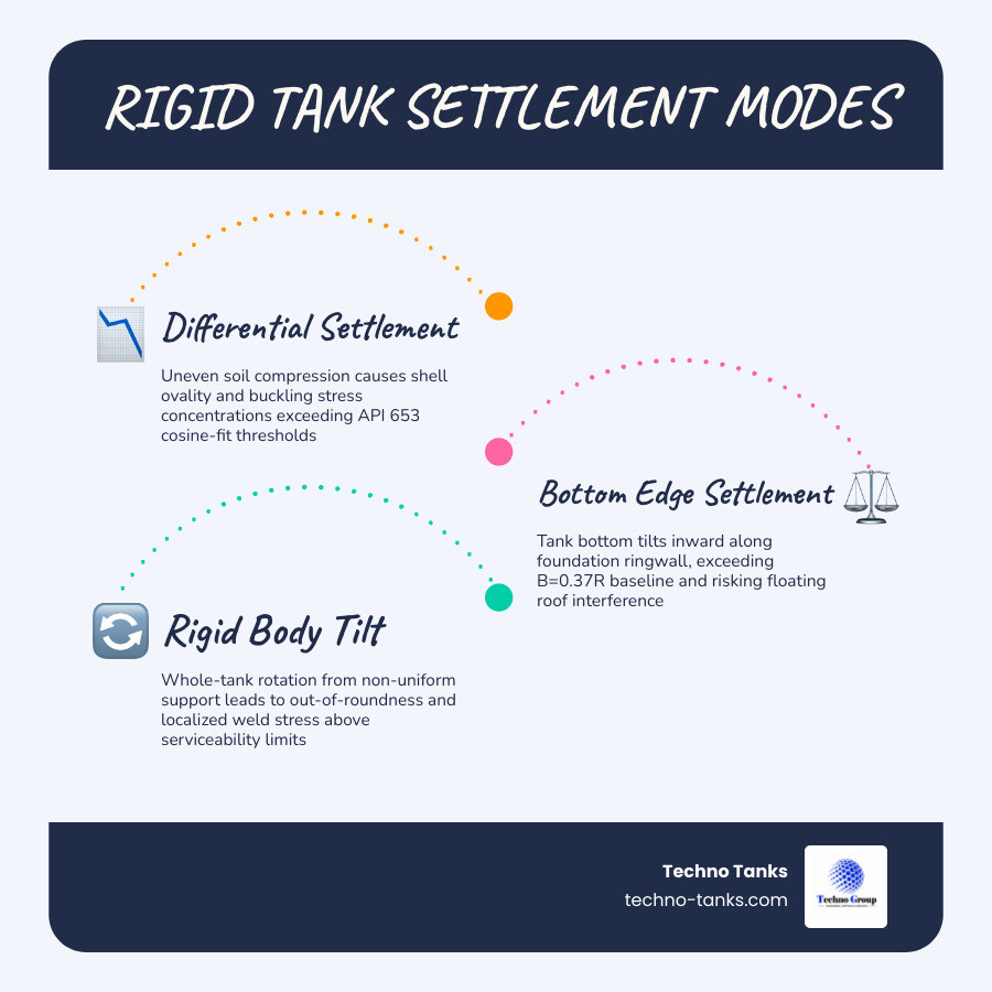
To properly evaluate a tank, engineers must distinguish between the primary settlement modes:
- Uniform Settlement: The entire tank settles evenly into the ground. While this does not induce structural stresses in the shell itself, it can shear attached piping, utility lines, and conduits if they lack sufficient flexibility.
- Rigid Body Tilt (Planar Tilt): The tank rotates as a rigid disk. This tilt increases the hydrostatic head on the lower side, shifting the liquid load and inducing minor out-of-roundness. The primary risk is the binding of floating roofs and the malfunction of liquid level indicators.
- Differential Shell Settlement (Out-of-Plane Settlement): This is the most destructive mode. It occurs when the tank shell settles unevenly along its circumference, creating a wavy, non-planar profile. This forces the shell to distort, generating high shear stresses, localized buckling, and severe out-of-roundness that can paralyze floating roofs.
- Bottom Edge Settlement: This occurs when the bottom plate near the shell-to-bottom corner joint settles sharply relative to the rest of the tank. It is often driven by the erosion of the foundation shoulder outside the tank or high localized loads (such as heavy snow loads transferred from the roof). This mode risks tearing the bottom plate or cracking the critical shell-to-bottom fillet welds.
API 653 Screening Criteria and the Cosine-Fit Method
API 653 Annex B provides the industry-standard framework for evaluating whether a settled tank can safely remain in service. The traditional screening method relies on the cosine-fit method (API 653 B.3.2.1).
In this procedure, elevation measurements are taken at equal spacings around the tank circumference. Engineers then fit a cosine curve to these points using regression analysis. The uniform settlement and rigid body tilt components are mathematically subtracted from the raw data. The remaining deviations represent the out-of-plane differential shell settlement.
However, the cosine-fit method has notable limitations:
- Sensitivity to Measurement Spacing: The calculated out-of-plane deflection is highly dependent on the number and spacing of the measurement points.
- Regression Fit Requirements: A reliable evaluation requires an $R^2$ regression coefficient of at least 0.9. If the settlement profile is highly irregular or localized, the cosine curve will not fit well, rendering the screening criteria overly conservative or inaccurate.
- Weld Orientation and Edge Curves: When evaluating edge settlement, the allowable limits depend heavily on the orientation of nearby bottom plate welds. Welds running parallel to the shell are more vulnerable to bending stresses than those running perpendicular. Engineers must subtract the original bottom design slope from the raw elevation data to isolate the true edge settlement displacement before comparing it to the allowable edge settlement curves in API 653.
Advanced FEA-Derived Methods for Evaluating Rigid Tank Structural Limits
To address the limitations of the cosine-fit approach, API 653 Annex B.3.2.2 introduced an alternative screening method derived by engineers Andreani and Carr. This FEA-derived method is based on a massive parametric study comprising over 3,700 finite element analysis (FEA) runs.
The Andreani and Carr method utilizes an arc-length approach that evaluates the shear strain in individual shell panels, removing the dependence on uniform measurement spacing. The acceptability criteria for this method were established using a 3% plastic strain limit at the critical joints and strict out-of-roundness tolerances to protect floating roof serviceability.
By accurately modeling the shell’s post-yield behavior, this FEA-derived method permits deliberate, justifiable reductions in conservatism. This allows operators to safely keep tanks in service that would otherwise fail the rigid cosine-fit limits, avoiding expensive and risky re-leveling procedures. For more on the operational risks of structural failures and how to avoid them, refer to Recycling Fuel Tanks: A Guide to Not Blowing Things Up.
Hydrostatic Loading and Deflection Limits in Rectangular Steel Tanks
Unlike cylindrical tanks, which resist internal liquid pressure primarily through efficient hoop (tensile) stress, rectangular steel tanks experience bending and shear. Under hydrostatic pressure, the flat vertical walls of a rectangular tank want to bow outward, a phenomenon known as bulging.
Bulging Limits and Serviceability Criteria
Bulging in rectangular tanks is primarily a serviceability concern, though excessive deflection can lead to weld cracking and structural failure at the corner connections.
In a real-world case study of a rectangular steel tank (measuring 8 m long, 1.5 m wide, and 2.2 m high resting on a concrete pad), FEA modeling showed a lateral deflection of 70 mm at the top channel. Over a 2.2 m span, this yields a deflection-to-span ratio of approximately 1/30. This is considered highly excessive compared to preferred industrial ratios.
To maintain structural integrity and prevent fatigue at the joints:
- AS 4100 (the Australian steel structures standard) recommends a deflection limit of span/250 for steel tanks, with up to span/500 for less ductile materials or high-vulnerability applications.
- An L/100 deflection limit is commonly used for the membrane deflection of thin sheet metal panels situated between rigid structural supports or external stiffeners.
- For concrete liquid-retaining structures, crack control is even more stringent to prevent leakage, as detailed in Early Age Concrete Volume Changes and Thermal Actions in Practice of Reinforced Concrete Liquid Tanks Design .
- Furthermore, secondary containment structures must be designed to withstand catastrophic hydrostatic surges, as outlined in the Chapter 4 Secondary Containment and Impracticability – EPA guidelines.
Modeling Membrane Action and Stiffener Optimization
When analyzing rectangular tanks, small-deflection theory (which assumes the maximum deflection is less than half the plate thickness) often leads to overly conservative, heavy designs. In reality, as a flat plate deflects under hydrostatic load, it begins to behave as a membrane, carrying loads through in-plane tensile forces rather than pure bending.
To optimize the design:
- FEA Modeling: Engineers use plate elements in FEA software that capture both membrane and bending attributes. This allows the model to account for the beneficial “catenary” or membrane action, which naturally reduces bulging.
- Stiffener Optimization: Instead of simply increasing plate thickness—which is often uneconomical—designers add external stiffeners (such as steel channels or angles). The spacing and moment of inertia of these stiffeners are optimized to keep deflections within AS 4100 limits.
- Connection Detailing: Corner connections must be checked for force transfer. Modeling connections as pinned rather than fully fixed provides a conservative estimate of member stresses, ensuring that the joints do not unzip under peak hydrostatic loads. Similar structural optimization methodologies for thin-walled vessels are explored in Structural Performance Optimization and Verification of an Improved Thin-Walled Storage Tank for a Pico-Satellite .
Seismic Response and Sloshing Dynamics in Cylindrical Tanks
During a seismic event, the liquid inside a cylindrical tank does not move as a single rigid mass. Instead, the fluid dynamic response is split into two components: the impulsive mass (the lower portion of the liquid that moves in unison with the tank shell) and the convective mass (the upper portion of the liquid that sloshes back and forth near the surface).
Aspect Ratios (H/D) and Convective Frequencies
The ratio of the liquid height to the tank diameter ($H/D$), known as the aspect ratio, dictates how the tank responds to seismic energy:
- Slender Tanks ($H/D > 1$): Slender tanks have a larger portion of impulsive mass. The convective (sloshing) frequency increases asymptotically as the tank diameter decreases. Because slender tanks have a smaller water surface area relative to their height, the sloshing wave height is lower, but the hydrodynamic pressures exerted on the shell are highly concentrated near the base, increasing the risk of “elephant’s foot” buckling.
- Broad Tanks ($H/D < 1$): Broad tanks have a dominant convective mass component. The sloshing frequency is lower, meaning they are more susceptible to long-period ground motions. The sloshing wave heights can be massive, risking damage to fixed or floating roofs.
These seismic actions and their effects on steel shells are rigorously codified in EN 1993-4-2:2007 Eurocode 3: Design of steel structures – Part 4-2: Tanks.
Resonant Sloshing and Critical Seismic Failure Thresholds
When the dominant frequency of seismic ground motion matches the first convective natural frequency of the liquid, resonant sloshing occurs. This generates extreme hydrodynamic pressures.
In a comprehensive dynamic study, cylindrical steel tanks with $H/D$ ratios ranging from 0.5 to 1.5 were subjected to harmonic base excitations with displacement amplitudes from 5 cm to 50 cm. The results identified three distinct structural zones: safe, yielding, and ultimate failure.
- Yielding Thresholds: Under resonant conditions, a tank with an $H/D = 1.2$ exhibited structural yielding within just 2 seconds when subjected to resonant seismic excitations featuring four loading peaks of 0.3g over a 4-second duration.
- Ultimate Failure Loads: If peak ground displacement (PGD) amplitudes are sustained, the high-stress concentrations at the base of the shell lead to plastic collapse (buckling) or weld tearing. Two-way fluid-structure interaction (FSI) modeling is required to accurately capture how the flexibility of the steel shell interacts with these sloshing waves, as rigid-wall assumptions tend to underestimate the peak hydrodynamic stresses.
Mobile and Specialized Rigid Tank Design Considerations
Rigid tanks mounted on vehicles or heavy machinery face unique structural challenges. Unlike stationary ground-supported tanks, mobile tanks must endure continuous dynamic forces, multi-directional accelerations, and severe vibration fatigue.
Articulated vs. Rigid-Frame Water Tanks
In heavy construction and mining, water tanks are used for dust suppression and road maintenance. The choice between articulated and rigid-frame chassis configurations fundamentally alters the structural demands on the tank.
| Feature | Articulated Water Tanks | Rigid-Frame Water Tanks |
|---|---|---|
| Typical Capacity | 5,000 to 9,000 gallons | 10,000 to 24,000 gallons |
| Chassis Flexibility | High; oscillating hitch isolates tank from frame twisting | Low; tank is mounted directly to a rigid, single chassis |
| Maneuverability | Excellent in confined spaces and rough terrain | Limited; designed for long hauls and higher speeds |
| Center of Gravity | Higher; elevated mounting systems | Lower; tank mounts directly to the frame rails |
| Baffling Systems | Standard transverse baffles | Heavy longitudinal and transverse baffle matrix |
| Construction | Single-welded or bolt-on assemblies | Double-welded (inside & out) heavy-plate steel |
Because rigid-frame tanks carry massive volumes (up to 24,000 gallons), the dynamic sloshing forces during braking and cornering are immense. These tanks require robust internal baffling systems—featuring both longitudinal and transverse baffles tied directly to the bulkheads—to control water movement and prevent the liquid from destabilizing the vehicle.
Dynamic Response and Rigid Tank Structural Limits in Transportation
Vehicle-mounted tanks operate in an environment dominated by random vibration. Industry data indicates that approximately 15% of mechanical failures in heavy transport vehicles are related to vibration fatigue.
To prevent structural failure:
- Vibration Stress Limits: According to standards such as JB/T 4730-2019, the allowable stress in a pressure-bearing tank structure under dynamic transportation loads must not exceed 80% of the material’s yield strength (typically limiting active stresses to under 164 MPa for standard 205 MPa yield steel).
- Regulatory Compliance: Under U.S. federal regulations 49 CFR § 178.337-3 – Structural integrity. | Electronic Code of Federal Regulations (e-CFR) | US Law | LII / Legal Information Institute and 49 CFR 178.345-3 – Structural integrity. , cargo tanks must be designed to withstand specific acceleration factors:
- Normal Operating Loadings: $0.35g$ longitudinal and $0.2g$ lateral.
- Extreme Dynamic Loadings: $0.7g$ longitudinal and $0.4g$ lateral.
- Accident Impacts: The tank must survive a $2g$ longitudinal deceleration without structural breach, with stresses limited to the lesser of the yield strength or 75% of the ultimate tensile strength.
- FEA Verification: Engineers utilize power spectral density (PSD) analysis to model road excitations (such as C-class road profiles). This helps identify resonance-prone frequency bands (typically 0–5 Hz and 5–15 Hz) and optimize mounting pads, ensuring they extend at least 2 inches in all directions to distribute localized stresses, as analyzed in Analysis of dynamic response characteristics of vehicle-mounted tank based on the finite element method – Extrica .
Frequently Asked Questions about Rigid Tank Structural Limits
When should engineers escalate from API 653 screening to API 579 Level 3 FFS analysis?
Engineers should escalate to an API 579 Level 3 Fitness-For-Service (FFS) assessment when:
- The measured differential or edge settlement exceeds the simplified screening limits of API 653 Annex B.
- The settlement profile is highly localized or exhibits complex twisting patterns that cannot be accurately characterized by a cosine-fit or standard arc-length curve.
- The settlement occurs near critical rigid piping penetrations, sumps, or flush clean-out nozzles, where localized plastic strain and stress concentrations are highly elevated.
- A Level 3 FFS, which utilizes advanced non-linear FEA, is required to prove that the localized plastic strain remains safely below acceptable limits (typically 3%) for continued operation.
What are the typical deflection limits for rectangular steel tanks under hydrostatic pressure?
The industry standard for rectangular steel tanks resting on the ground is to limit lateral wall deflection (bulging) to span/250 per steel design codes like AS 4100. For highly aesthetic or critical applications, this may be tightened to span/500. For individual thin-walled membrane panels supported by a heavy structural frame, a limit of L/100 (where L is the span between stiffeners) is widely accepted.
How do weld orientations affect allowable edge settlement curves in API 653?
Weld orientation is a major factor in the fatigue life of a tank bottom. When a tank bottom plate settles near the shell, the plate undergoes bending. If a lap weld or butt weld runs parallel to the tank shell, the bending stresses act directly across the weld joint, increasing the risk of weld toe cracking.
Consequently, API 653 allowable edge settlement curves are significantly more conservative (allowing less settlement) when welds are parallel to the shell compared to when they run perpendicular, where the bending stresses run along the length of the weld rather than trying to pull it apart.
Conclusion
Understanding rigid tank structural limits is essential for maintaining safety and operational continuity in demanding industrial, marine, and commercial environments. From the complex soil-structure interactions of foundation settlement to the violent hydrodynamic forces of seismic sloshing and road transport, rigid tanks are constantly pushed to their physical boundaries.
However, there are many scenarios—particularly in marine auxiliary fuel storage, remote commercial operations, and temporary fuel-transfer applications—where permanent rigid tanks are impractical due to space constraints, weight limitations, or installation costs.
In these situations, flexible fuel bladders and collapsible fuel storage systems offer a reliable, highly adaptable alternative. Techno Tanks manufactures high-performance flexible fuel bladders and collapsible storage systems designed to carry, store, or transfer fuel safely without the rigid structural vulnerabilities of traditional steel or plastic tanks.
Constructed from advanced, flexible TPU materials and available in capacities ranging from 30 to 3,000 gallons, these systems are compatible with both gasoline and diesel (depending on the configuration). They offer a space-saving, custom-sized solution that eliminates the risks of weld cracking, shell buckling, and foundation settlement.
To learn more about how flexible systems compare to traditional rigid storage, read our guide on Fuel Bladder vs Fuel Tank, or discover how smaller, highly portable options can support your operations in Why a 30 Gallon Plastic Tank is Your Storage MVP.
For precise pricing based on your specific fuel storage, transfer, sizing, and custom application requirements, contact Techno Tanks today to request a tailored project quote.

